

|
Don’t be scared by words like resistors, capacitors, and weird symbols like Ω; electronics are easy. Once you understand the basics there’s no end to the types of cool projects you can make! The Interrogator 3000 is a great project to introduce you to electronics, and with the provided circuit diagram you don’t even have to worry about confusing circuit boards.
You should build this and have it around for emergencies when you absolutely need to know the truth. Most electronic stores will have the parts you need: the speaker, nine volt battery clip, wire, and paper clip should be easy to find in junk you have laying around. Click here to buy a kit with all the parts you need. |
|
The lie detector works on a principle called galvanic skin response. Basically, it detects sweat, which usually happens when someone lies. Sweat increases the conductivity (ability to let electricity pass through) of your skin. Your sympathetic nervous system controls the sweat glands on your fingertips and is completely subconscious (not controlled by you). When caught in a lie, these fight-or-flight nerves are alerted. Your body will sweat a little. The sweat will cause the electricity to flow in higher amounts and produce a higher pitched sound from the Interrogator 3000.
Once built, to test this out put your fingers in the paperclips and connect the battery. Remember the pitch of the tone. Now remove the paperclips and lick your fingertips. Try it again. The pitch should be higher.
The problem with this lie detector is that you can’t fake lies. If I said, “My name is Barack Obama,” it wouldn’t increase the pitch. This is because my nerves were not aroused, I was just joking around. The more you can get someone to take your lie detector seriously, the better.
This is based on Slater Harrison’s lie detector on sciencetoymaker.org. Check out his website for many more fun and inexpensive gadgets you can make.
Materials: (Can be purchased here.)
*82KΩ resistor
*4.7KΩ resistor
*3906 transistor
*3904 transistor
*.01 mfd ceramic disk capacitor
*9 volt battery clip
*9 volt battery
*scrap cardboard
*2” Ω speaker (many other speakers will work too)
*18 gauge solid wire with jacket/coating
*2 alligator jumper cables
* a photocopy of the circuit template (or print one from below)
*card stock (like from junk mail)
* 2 paper clips (metal ones, with no plastic coating)
Tools:
*glue stick
*thumbtack
*thumbtack
Steps:
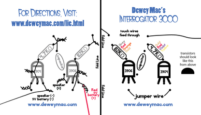
1. Make a copy of the circuit template. Be careful not to enlarge it. Cut along the outside line.
2. Fold it over on the fold line. Add glue to the underside of each half of the fold sections. Glue circuit template around a
piece of cardstock from some junk mail. This will make your circuit board stronger.
3. Place the circuit template flat on your scrap cardboard. Carefully use a thumbtack to poke a hole on every black dot. There are 16 total.
4. Add the transistors (half circles) to their correct spot on the circuit board. Make sure that the flat part of the transistors faces you.
5. Add the capacitor (round) through the labeled holes, it doesn’t matter which leg goes through which hole.
6. Add the resistors (long and skinny). Make sure you match the colors. As long as you are using the correct resistor, it doesn’t matter which leg goes through which hole.
7. Make a jumper cable by cutting a small section of wire and stripping the ends of the plastic coating. Insert your short (only a
few inches long) jumper cable where indicated at the bottom of the circuit template.
8. Poke your touch cables through the circuit template where indicated. Make sure each end is stripped. These touch cables will be attached to paper clips later.
9. Turn the circuit template over. Following the images, twist together the wires and components making sure that twisted wires don’t touch each other.
10. Twist the red wire from the 9 volt battery clip where indicated. Twist the black wire from the 9 volt battery clip where indicated.
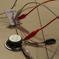
11. Add the alligator clips according to the template. One should connect to the positive (+) terminal of the speaker and then to
the wires by “speaker (+).” The other wire connects the speaker’s negative (-) terminal to the wires on the circuit template near “speaker (-).”
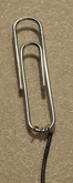
12. Twist the stripped end of the touch wires around the paper clips. Make sure it is the short end of the paperclip that has one
loop, not two.
the wires by “speaker (+).” The other wire connects the speaker’s negative (-) terminal to the wires on the circuit template near “speaker (-).”
12. Twist the stripped end of the touch wires around the paper clips. Make sure it is the short end of the paperclip that has one
loop, not two.
13. Place the paperclips together. Connect the battery to test the circuit. If you don’t hear a sound, quickly disconnect the battery so you don’t burn out the transistors. Check that all of your components were added in the correct spot and make sure your transistors are facing the correct way. Continue to test and check until it works.
14. Put a finger from each of your subject’s hands in the two paper clips. Ask them questions. Find the truth, the ugly truth.
14. Put a finger from each of your subject’s hands in the two paper clips. Ask them questions. Find the truth, the ugly truth.
Options:
When your Interrogator 3000 is working, try building a cool enclosure for it. You can use a pencil box, cigar box, can of
SPAM, or really anything. Be creative. Make sure it looks intimidating to get the whole truth, and nothing but the truth.
If you want, wrap the touch wires around a pencil or marker to give them a cool spiral look.
SPAM, or really anything. Be creative. Make sure it looks intimidating to get the whole truth, and nothing but the truth.
If you want, wrap the touch wires around a pencil or marker to give them a cool spiral look.
